Traditional VPN programs are inefficient and not scalable, mainly due to their star topology architecture. Every packet in the network has to go through a VPN server, which can be a bottleneck when there’s a spike in traffic or there are lots of nodes connected to the server. Furthermore, they tend to be vulnerable, and a simple misconfiguration can lead to a huge security hole in a system. In this paper, we propose a peer to peer layer 3 VPN with mesh topology, where nodes directly and securely send packets to each other without the packet going through a central VPN server. We name this VPN software ’Badger’ in this paper.
Keywords: peer-to-peer; VPN; IPSec, OpenVPN
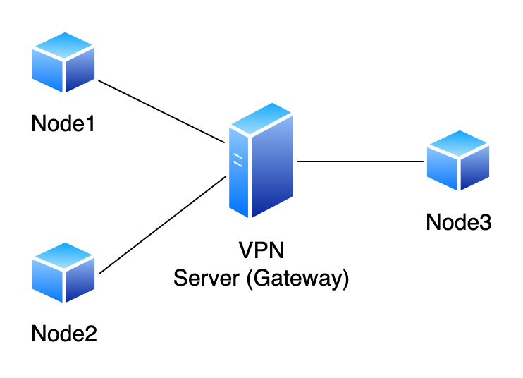
Predominate VPN solutions like OpenVPN (Feilner 2006) and IPsec (Doraswamy and Harkins 2003) based VPNs have a central server for relaying packets and node discoverability, among various other functions. For a packet to tunnel from one node to another, it has to be relayed through the central server before reaching the destination node(Bollapragada, Khalid, and Wainner 2005). Whenever there are many nodes connecting to the server or there is an influx in traffic, the central server can be a huge bottleneck, slowing down the entire network(Pudelko et al. 2020). This architecture has the obvious drawback of not being able to scale the network when required because of the inherent limitations of a star-topology architecture.
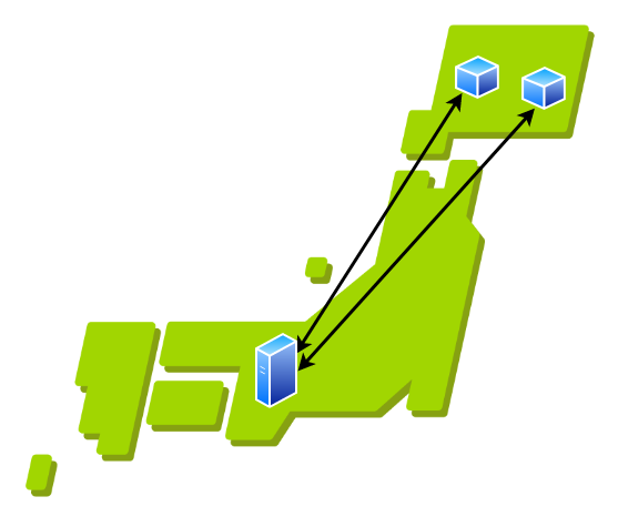
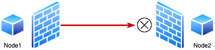
(Figure 1 demonstrates a simple star topology VPN architecture.) For example, let us consider a situation where two nodes are geographically close to each other but the central server is far from both nodes. If the nodes want to communicate, all packets have to go through the central server, which is not located close to the nodes, resulting in higher latency and inefficient traffic routing (this is demonstrated in figure 2). In this situation, it would be ideal if we could tunnel packets directly between nodes and rely only on the central server to exchange network information. (This is demonstrated in figure 3).

It is also not possible to scale this architecture horizontally, and vertical scaling ends up costing a lot, especially if you are using a proprietary solution from a vendor (Nakahara, Fukuyama, and Katoh 2006). They are also very complicated, and a simple misconfiguration of a security parameter can leave the entire network vulnerable to a host of attacks (Rahimi and Zargham 2012). To overcome these limitations, we consider a simple peer-to-peer VPN architecture with mesh topology, where nodes establish a direct encrypted tunnel within themselves without having to tunnel packets through a central server.
We refer to the VPN client program as ’Badger’.
We refer to a netowrk device that the VPN client program (Badger) will be running on as ’Node’.
’IEX server’ is the name of the program that helps nodes with peer discoverability, firewall circumvention, and NAT traversal.
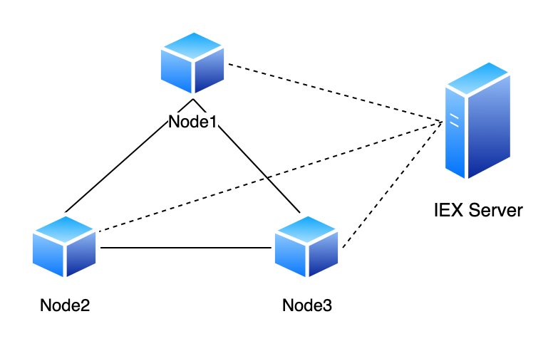
For efficient communication between nodes, we consider a architecture where nodes don’t need a central server for packet tunneling. However, we do need a central server for node discoverability and to facilitate various other functions such as NAT traversal and coordinating communication among nodes. But the actual data packets never go through the central server; they are sent directly from one node to another using a secure encrypted tunnel. In our implementation, we call this server ’IEX server’ and every node in the network relies on this server to know about other active nodes in the network. The IEX server is also used for NAT traversal, so that we don’t have to configure port forwarding manually for nodes to receive requests. This architecture is demonstrated in Figure 4. The dotted lines represent the communication of network information, while the solid black lines represent the tunneling of packets between nodes.
Achieving peer-to-peer connection in an ipv4 network is challenging (Ford, Srisuresh, and Kegel 2005). For example, due to NATs, it is difficult for nodes to receive data from other nodes without manual configuration (i.e. port forwarding). We also have to consider firewalls that block all incoming traffic (Gouda and Liu 2005).
To help solve these issues and facilitate a reliable peer-to-peer connection, we use the IEX server. The following texts explain how we achieve this in detail and how the VPN software works.
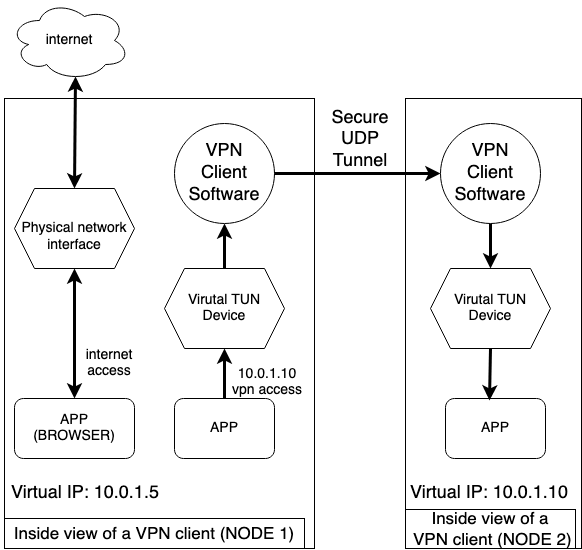
To tunnel a packet, we first need a way to intercept it. But we only want to intercept packets that are meant to be tunneled to nodes inside the VPN network and not intercept packets that are not meant to be tunneled (i.e. traffic that is not destined for nodes in the network). In order to achieve this we designate a subnet space for VPN connections, and for each node in the network, assign a virtual IP to the node from the subnet. For example, if the subnet is 10.0.0.0/16 we can have 65,536 unique IP, which in turn means that we can have 65,536 nodes in the network. Every node is assigned a unique virtual IP address that is different from its local or global IP address. Then, we can setup a virtual network interface so that all traffic destined for addresses within the subnet will be routed to the interface. Now, we can configure our VPN program to intercept all packets sent to this virtual interface.
For example, in figure 5 when Node1 tries to send something to Node2 using Node2’s virtual IP, the VPN software running in user space captures the packet and tunnels it to Node2. On Node2’s side the VPN software intercepts the packet and hands it over to the virtual network interface by writing the packet to the tun file. However, other packets that are not destined to a node in the VPN network are not intercepted by the software.
To intercept the packets that are routed to the virtual interface we
use a mechanism provided by the Linux kernel called TUN (Turner 2019).
First, we create a virtual interface and assign it a virtual IP with the
following command:
/sbin/ip addr add 10.0.0.10/16 dev vdevice
Then we enable the interface with the following command:
/sbin/ip link set vdevice up
Now, if we issue a appropriate ioctl() system call and read the file at
/dev/net/tun, our program can receive packets that are sent
to the virtual network interface, and conversely if our program receives
a packet from another node we can write that packet to the file and the
network interface will receive it.
The IEX Server is a simple UDP server that keeps track of all client nodes that want to actively join the network. It keeps information about the node’s virtual IP, and public IP and port from which the node is sending the heartbeat message (which will also be the IP and port the node is listening at for UDP connections). In our implementation the server saves these information in a simple in-memory database.
It also periodically checks for stale information and tries to maintain the latest information about the network. For example, if a node does not send a heartbeat signal within a set amount of time, the IEX server will delete that node from it’s database. The IEX server stores the following information about each node.
Public IP address and port at which the node listens for UDP connections.
Virtual IP that is assigned to the node.
Last time the node sent a heartbeat message to the IEX server.
The IEX server then relays all the above information to every node in the network. This is how the nodes become aware of other nodes. The server sends this information to the same IP address and port the client node uses to send the heartbeat messages.
As explained in Section 3.1, we only capture packets that are destined for some node inside the VPN network. The VPN client program constantly waits for packets and when it receives a packet it looks at it’s destination IP address. It then searches it’s database to get information about the destination node, such as which UDP address and port the node is listening at. Once the client program is aware of this information, it tries to open a secure UDP socket to the destination node, this connection is encrypted using the dTLS (Kothmayr et al. 2013) protocol for security. Once the connection is established, the source node tunnels all the packets to the receiving node. On the receiving side, the VPN client writes the received packets to the virtual network interface.
For security, we use the dTLS protocol (Kothmayr et al. 2013) to encrypt the UDP connection between the nodes. More specifically we use the AES encryption scheme to encrypt the packets using a pre-shared key. This key is specified at each client node while starting the VPN program.
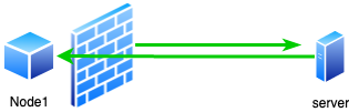
Peer-to-peer connections are hard to achieve in a typical IPV4 network because of how NAT devices operate (Egevang and Francis 1994). For example, consider a situation where two nodes want to communicate with each other. In figure 6 we see that node2 is aware of the IP address and port node1 is listening at, so it tries to open an UDP connection. But because the NAT of the network node1 belongs to does not know where to route the packet, it is dropped.
One simple solution to this problem would be to configure a port forwarding rule in the NAT device a node belongs to, such that a packet that is destined to a certain port is routed properly to a certain device inside the network. Unfortunately, this solution is not scalable. If you have hundreds of nodes in a VPN network, you would have to manually configure the NAT settings for each node’s network.
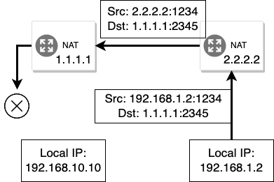
To solve the NAT problem without requiring manual configuration, we use the IEX server. Usually whenever there is an outgoing traffic from a network device, the NAT dynamically allocates a port for that connection (Figure 7) and keeps track of which device the port is allocated for. Now, using this information, whenever the NAT device receives something on that same port, it can route it to the appropriate device. In our program, we leverage this mechanism to achieve reliable peer-to-peer connection.
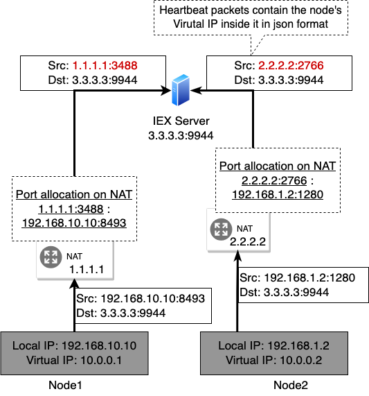
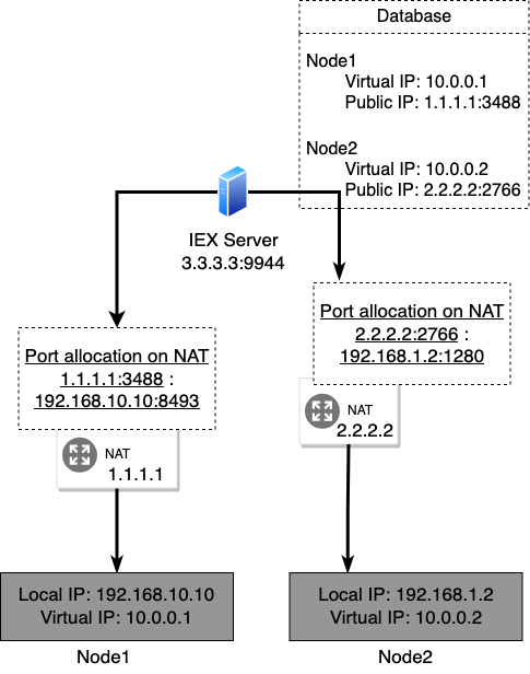
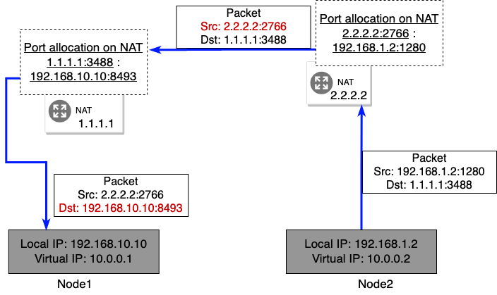
Specifically what we do is first a node makes an initial connection to the IEX server, sending it the virtual address it wants the IEX to assign to it. Then, the IEX server receives the request and by looking at the source IP address, it becomes aware of public IP address and the port number the NAT has allocated for the node. It then stores this information in it’s database, it does this for all the nodes and finally it periodically sends this information to every node in the network, so that each node is aware of every other nodes in the network and what private and public IP address they have and what ports they are listening on. Now, since the NAT device has reserved and assigned a port for a node, any incoming packets on that port will be routed properly to it. Since every node also listens on the same port they used to initiate a connection with the IEX server, if a node on another network tries to connect to some node using the IP address and port it got from the IEX server, the connection will be properly routed by the destination node’s NAT.
Another obstacle we have to consider when establishing a peer-to-peer connection are firewalls. Most firewalls work by blocking any incoming connection if there was no prior outgoing request from the same port (Gouda and Liu 2005), this is demonstrated in Figure 10. The way stateful firewalls achieve this is by maintaining a state of all outgoing connections, and when they receive an incoming connection, they refer to the state and only allow it to go through if there was a previous outgoing record in the state, as demonstrated in Figure 11. We can leverage this mechanism to circumvent the firewall to achieve a peer-to-peer connection.
Whenever two nodes want to communicate, we choose a leader node who will be initiating the connection. There are various ways to accomplish this but for simplicity we designate the node with the larger virtual IP address as the leader. For example, if there are two nodes with the IP address 10.0.0.1 and 10.0.0.10, the latter would be the leader.
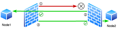
In Figure 12 we can see that Node1 is the leader. Here, the leader node sends an initial connection, represented in the figure by the red line, which will be blocked by Node2 because there was no prior outgoing connection from Node2 to Node1. Now, right after this, regardless of the success of the initial connection, Node2 sends an request to Node1 on the same port Node1 initiated the initial connection from, which Node1’s firewall assumes is a response for the prior request to Node1 and allows it. Then, Node1 can again send a request to Node2, which Node2’s firewall will assume is the response to the prior request to Node1. Now we have a situation where firewalls on both sides allow connection to and from each other, enabling us to achieve a reliable peer-to-peer connection.
In this section we elaborate further on the implementation details of our software. We have two different software for helping us achieve a VPN network.
In our reference implementation there are two separate programs. One is called ’IEX Server’, and as explained in Chapter [iex], it is responsible for peer discoverability, firewall circumvention and NAT traversal.
Another program is the VPN client software we call ’Badger’. This program is responsible for creating tunnels and sending packets to other nodes in the network.
The implementation of the server is fairly straightforward. Here we explain the server’s features and how we implement them.
For peer discoverability, the server has to relay the latest network information to the nodes. In this section we go into details of how we collect that information.
The server has to collect information about each node and store it inside a ’database’. In our implementation, we store it in a simple hashmap. We use the public IP address of a node as the key and the value is a struct that holds all the metadata about a node such as it’s private IP address and when the last connection from that node happened, this struct is defined as follows.
type NodeInfo struct {
    LastSeen  time.Time `json:"-"`
    PublicIP  netip.AddrPort
    PrivateIP netip.AddrPort
    VirtualIP netip.Addr
}
Our server constantly listens for UDP connections from nodes, and it expects a UDP packet, with body of the packet containing data in JSON format (Bray 2014), we call this packet a heartbeat message. An example of a hearbeat message from a node is shown below.
{
    "VirtualIP": "10.0.0.10",
    "PrivateIP": "192.168.10.100"
}
When this message is received, the server extrapolates the node’s
public IP address and port from the UDP header. We can assume that this
is the address and port combination that the node’s NAT has allocated to
it, and can be subsequently used to send it packets, with the guarantee
that it will be forwared properly from the NAT to the node. Then the
server fills all of this information in the NodeInfo struct
and stores it in the hashmap.
The server repeats this process for all the nodes. By the end of this process, the server is in a state where it has information about every node in the network. Then, it has to relay this information to nodes so that they are aware of each other.
Once we are done with collecting the information, we have to relay it. Here we explain how we achieve it in our reference implementation.
The data we relay to the nodes is a list that contains information about each node and the index in the list where the receiving node’s information is at. The data structure is defined as follows.
type NetworkMap struct {
    Nodes   []*NodeInfo
    MyIndex int
}
The following code is responsible for relaying the node information.
// relay information about nodes in the network to all nodes in the network
func (nw *Network) relayNodeInfo() {
    nw.rwMutex.RLock()
    defer nw.rwMutex.RUnlock()
    nodeInfo := make([]*NodeInfo, 0, len(nw.nodes))
    for _, node := range nw.nodes {
        nodeInfo = append(nodeInfo, node)
    }
    relayInfo := NetworkMap{Nodes: nodeInfo}
    relayInfo.MyIndex = 0
    for _, node := range nodeInfo {
        relayByte, err := json.Marshal(relayInfo)
        if err != nil {
            panic(err)
        }
        nw.conn.WriteToUDP(relayByte, net.UDPAddrFromAddrPort(node.PublicIP))
        relayInfo.MyIndex += 1
    }
}
In the above code, we loop over a list of nodes and send each node the list that we are looping over, which contains information about the nodes. We also need to attach the index data that represents where in that list the node’s own information resides. The reason we do this is so that the receiving node can ignore it’s own information. Instead of sending the entire list, we could also make a new list without the receiving node’s information in it, but this is inefficient because we would have to make a lot of memory allocations for the new lists.
The above function runs every 5 seconds. It also runs every time there is a change in network information to ensure that nodes always have the latest information.
Whenever a node disconnects from a network, the server is responsible for deleting its data from the database. To achieve this feature, we check how much time has elapsed since the last heartbeat message of a node. If this time exceeds the timeout duration, the node is deleted from the database. The timeout duration is set to 30 seconds in out implementation. The following code runs every 30 seconds, and after a change in network configuration (i.e. a new node joins the network).
func (nw *Network) timeOutInactiveNodes() {
    nw.rwMutex.Lock()
    defer nw.rwMutex.Unlock()
    now := time.Now()
    for key, nodeInfo := range nw.nodes {
        if now.Sub(nodeInfo.LastSeen) > nw.timeOutDuration {
            delete(nw.nodes, key)
        }
    }
}
Whenever a node is deleted from the database, the server sends the latest network information to all the nodes so they are aware of the changes.
The client program is responsible for receiving the network information from the IEX server and tunneling packets to other nodes. In the following texts we explain how we achieve this.
The client program has to receive information about all the nodes in the network from the server and also send a heartbeat message periodically so that the server is aware of its information. The program also periodically sends a heartbeat message in the format described in the above text. Through this message, it notifies the server about the private IP it wants to use and its local IP address. Because the server removes a node from the network when it hasn’t received a heartbeat from it within a certain time frame, the client program will periodically send a heartbeat message to it.
The client program also periodically receives information about other nodes. It stores this information in a hashmap. The key of the hashmap is a node’s private IP address and the value is a UDP connection to the respective node. We use this hashmap as a connection pool; we will explain this in detail in the following chapters. Whenever there is an outgoing packet to a node in the network, the IP address in the destination field of the header, which is the private IP of the destination node, is used for lookup, and a connection to that node is retrieved from the hashmap.
The client program receives the following data about the network from the server.
{
    "Nodes": [
        {
            "VirutalIP": "10.0.0.10",
            "PrivateIP": "192.168.10.100:3000",
            "PublicIP": "1.1.1.1:4400",
        },
        {
            "VirutalIP": "10.0.0.20",
            "PrivateIP": "192.168.10.200:3000",
            "PublicIP": "2.2.2.2:4400",
        }
    ],
    "MyIndex": 0
}
The MyIndex field in the above data represents the
position of the receiving node’s own data in the Nodes
field. A node must discard its own data. Once these data are received,
the node starts to open an connection to the other nodes, this is where
the firewall cirmunvention procedure also takes place. We will not go
into the details of this process as it is already explained in detail in
the Architecture section.
Connection to a node is encrypted using the Pion dTLS library (Pion 2022), and once a encrypted connection is established, it is put into the connection pool hashmap. In our program, we store this information as follows:
type NodeConnectionPool struct {
    connectionsVirtualIP map[netip.Addr]*NodeConnection
    connectionsPublicIP  map[netip.AddrPort]*NodeConnection
    mut                  sync.RWMutex
}
The connectionsVirtualIP is a hashmap used for looking
up and retrieving connection to a node by its virtual IP, and the
connectionsPublicIP is for retrieving the connection to a
node by its public IP address and port. Whenever a node is removed from
the network by the IEX server, we also close the connection to the
removed node and remove the corresponding data from the connection
pool.
As explained in Section [capture-packet-tunnel], we use TUN to capture outgoing packets from the virtual network device.
First, we create a virtual network device with the following commands. This command is executed automatically by the client program when it starts.
/sbin/ip addr add 10.0.0.10/16 dev vdevice
/sbin/ip link set vdevice up
Then, we read from the device we just created. The following code performs an appropriate iotcl call and retrieves a file descriptor from the kernel, which we will use to read packets from.
tunfd, err := unix.Open("/dev/net/tun", os.O_RDWR, 0)
if err != nil {
    log.Fatal(err)
}
ifr := ifReq{}
ifr.Flags = IffTun | IffNoPi
copy(ifr.Name[:], name)
_, _, errno := unix.Syscall(
    unix.SYS_IOCTL, uintptr(tunfd),
    uintptr(unix.TUNSETIFF),
    uintptr(unsafe.Pointer(&ifr)),
)
if errno != 0 {
    log.Fatal(errno)
}
unix.SetNonblock(tunfd, true)
// We will use this file descriptor to read from the tun
fd := os.NewFile(uintptr(tunfd), "/dev/net/tun")
Once we have the file descriptor, we can read from it and recieve packets from the virtual network interface. After reading packets from the interface, we extract the destination IP address from the packet header and search for a connection to the destination node in the connection pool. If a connection is found, the packet is sent to the node thought the UDP connection, and if not, the packet is simply dropped. We repeat this process in an infinite loop until the program ends. The code to do this is as follows.
pkt := make([]byte, 65535)
for {
    n, err := t.Read(pkt)
    if err != nil {
        t.lg.Println(err)
        panic(n)
    }
    header, err := ipv4.ParseHeader(pkt[:n])
    if err != nil {
        t.lg.Println("Error while parsing header", err)
        continue
    }
    vip := netip.MustParseAddr(header.Dst.String())
    node, ok := t.ncp.GetConnectionByVirtualIP(vip)
    if !ok {
        t.lg.Printf("Could not find node with IP %s in connection pool\n", vip.String())
        continue
    }
    payload := make([]byte, n)
    copy(payload, pkt[:n])
    node.queuePayload(payload)
}Whenever we receive a packet through UDP from a node, we simply write the packet to the file descriptor and the virtual network device will receive it. The code to do this is as follows.
b := make([]byte, 65535)
for {
    n, err := nc.conn.Read(b)
    if err != nil {
        nc.lg.Printf("Error when reading from remote %s\n", nc.virtualIP)
        nc.lg.Println(err)
        continue
    }

    nc.lastConnectedOn = time.Now()
    writeN, err := nc.tun.Write(b[:n])
    if err != nil {
        nc.lg.Println("Error when writing received bytes to tun")
        panic(err)
    }

    if writeN != n {
        nc.lg.Println("Not all bytes could be written to tun")
    }
}
Once the packet is received by the interface, it will be appropriately routed to the user space program.
Wireguard (Donenfeld 2017) is a protocol to achieve a secure network tunnel. However, Wireguard by itself is not a VPN software and needs a separate software to orchestrate the tunnels, or needs to be configured manually for every node in a network, which is not feasible. It is already implemented and integrated into the Linux kernel and is extremely efficient and performant. It uses various modern encryption protocols such as the Noise Protocol framework (Perrin 2018) to achieve a secure tunnel with minimal performance overhead.
We currently have an adhoc implementation for creating tunnel between nodes but using Wireguard for tunneling might give us better performance.
In this section, we evaluate the performance of our VPN. All the benchmarks were performed approximately at the same time, and on the same machines.
To test the performance of OpenVPN, we setup a OpenVPN server in Japan region. The server configurations are as follows.
client
dev tun
proto udp
float
nobind
cipher AES-128-CBC
comp-lzo adaptive
resolv-retry infinite
remote-cert-tls server
persist-key
persist-tun
The server is powered by an Intel i5 6400 CPU and has 12GB of RAM. It is allocated 1Gbps of bandwidth.
The IEX server is run on the same machine as OpenVPN.
The specification of the nodes is different depending on the tests. Details about them will be provided in each test section separately.
Here, we test how fast the Badger VPN is compared to a raw connection without the VPN. We also evaluate the NAT traversal and firewall circumvention features of our software
For this test, we use two personal computers connected to different networks. The bandwidth between the network is 1Gbps. The server will run on the same machine that OpenVPN is running on, as explained in [config-iex].
To test the raw speed, we need to configure the firewall and NAT of each node to allow packets from one another. Then, we setup a iperf3 server on one of the nodes with following command.
> iperf3 -s Once the node that will run the iperf3 server is setup, on another node, we run the test with the following command.
> iperf3 -c 152.108.113.186To test the speed with badger enabled and to evaluate other features like NAT traversal and firewall circumvention, we remove all the NAT port forwarding setting and firewall rules that we setup in the previous test. Then, we build the binary for the IEX server and run it with the following commands.
    > go build # build step
    > ./iex
We do not have to provide any arguments to the IEX server when running. When the server starts, it will listen to UDP connections on port 9944 by default. To receive packets from nodes, we must establish a port forwarding rule on the NAT to allow incoming packets to reach this port.
After the IEX server is successfully set up, we run the client program (badger) on both nodes with the following command.
Node 1 (San Francisco):
    > go build
    > ./badger --vip 10.0.0.10/16 --iex 54.250.148.195:9944 --psk psk-key
Node 2 (Singapore):
    > go build
    > ./badger --vip 10.0.0.20/16 --iex 54.250.148.195:9944 --psk psk-key
With the --vip argument we specify the node’s virtual IP
address. The --iex argument is used to specify the IP
address and port the IEX server is listening at, and the
--psk argument is for pre-shared key the clients will use
to encrypt the tunnels. The value of the argument --psk
should be the same for all the clients.
Once the nodes have connected, we set up an iperf3 server on a node with the following command.
> iperf3 -s -B 10.0.0.10After the server is running successfully, we start the benchmark from another node by executing the following command.
> iperf3 -c 10.0.0.10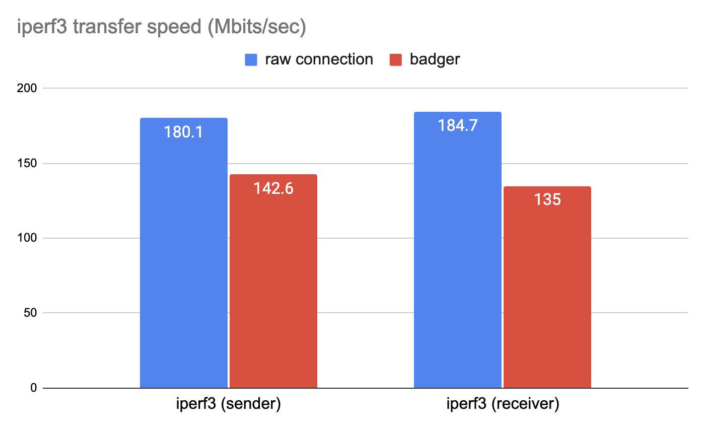
In the test our software was able to perform NAT traversal and firewall circumvention and establish a secure peer to peer tunnel within the nodes, without requiring any manual configuration.
The test results are presented in Figure 13. As we can see, badger is approximately 21% slower compared to a direct connection.
In this section, we compare Badger with OpenVPN.
To test the performance of the VPN, we setup two VPN nodes, with one node located in the Singapore region and another in San Francisco region. The client programs run on a VPS provided by DigitialOcean, and share the exact same specification. Each node is allocated 1 vCPU and 512 MiB of RAM and has 2Gbps of bandwidth.
The IEX server and the OpenVPN server will be located in Japan. Details on server configuration are provided in Chapters [config-open] and [config-iex].
First, we mesaure the performance of OpenVPN. In order to do so, we connect the two nodes to the server with the following command.
> sudo openvpn --config server.ovpnOnce the nodes have connected to the server, we run the iperf3 server on one node with the following command.
> iperf3 -sAfter the server is running successfully, we start the benchmark from another node by executing the following command.
> iperf3 -c 192.168.10.10To test Badger, we first run the IEX server with the following commands.
    > go build # build step
    > ./iex
After the server is up and running, we connect each client to the server with the following commands.
Node 1 (San Francisco):
    > go build
    > ./badger --vip 10.0.0.10/16 --iex 54.250.148.195:9944 --psk psk-key
Node 2 (Singapore):
    > go build
    > ./badger --vip 10.0.0.20/16 --iex 54.250.148.195:9944 --psk psk-key
After the clients are connectable, we run the iperf3 server on one of the clients with the following command.
> iperf3 -s -B 10.0.0.10After the server is running successfully, we start the benchmark from another node by executing the following command.
> iperf3 -c 10.0.0.10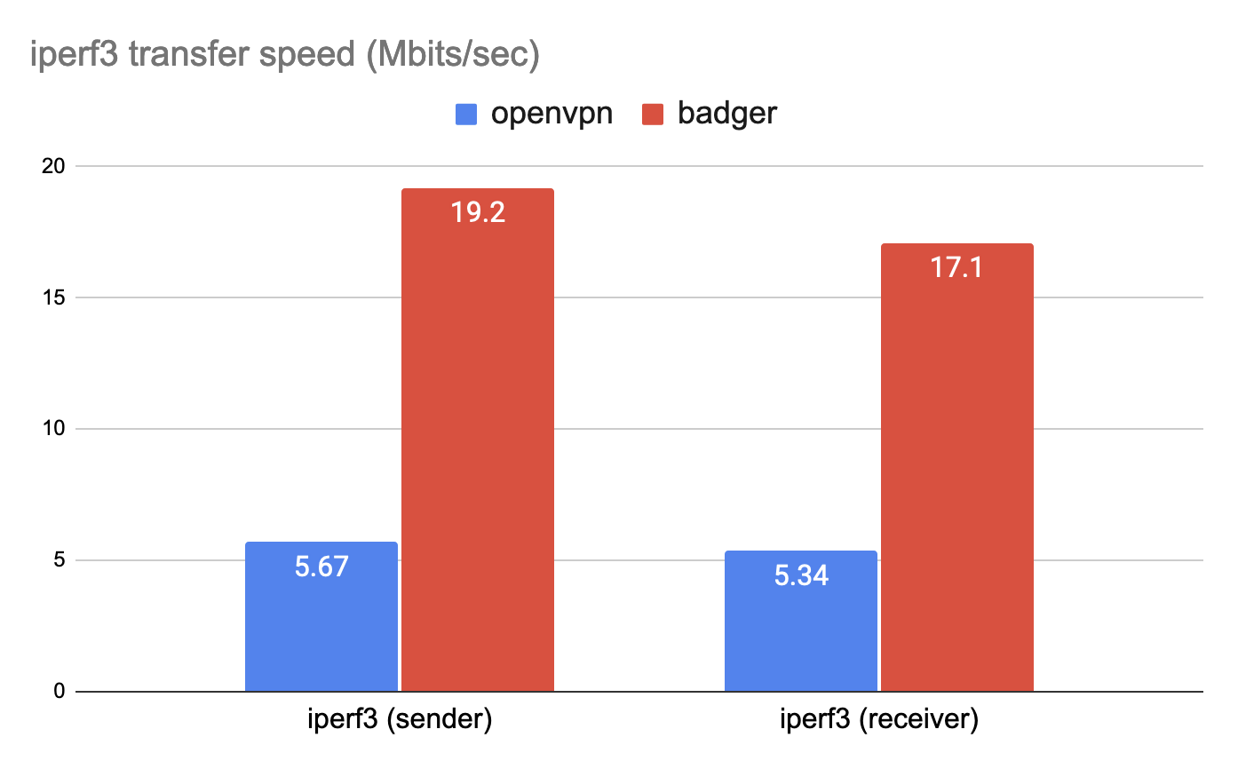
The results are presented in Figure 14. As we can see, Badger is approximately 330% faster than OpenVPN. In OpenVPN’s case the packets have to be sent to the server located in Japan and then relayed to the nodes. But with Badger, packets are sent directly between nodes, leading to higher throughput.
As we can see from the results in the above section, badger is slower when compared to a raw connection. This is partly because we are doing a lot of unnecessary memory allocation and copying in our program, which can be optimized further to improve the performance. There are also other parts of the program that could be improved for better performance.
But, when you compare badger with OpenVPN, the benefits of a peer-to-peer architecture are enormous. With badger we achieved a software that is multiple times faster than the alternative at the fraction of the infrastructure cost, while being very simple to deploy.
With some further improvements to the reference implementation, we believe that badger has a very real potential to be of real use in improving the efficiency of VPN networks in various environments.